
That's what my original AstroMaster motor drive decided to ponder during one freezing evening a few weeks back.
I was trying to get the tracking runing smoothly to take some new test photos. While adjusting the tracking speed I noted a fluctuation in the drive speed (easily apparent by the sound it made). That turned the anticipated photo session in to trying to figure out what was wrong with the drive. I could not get very far with my investigations in the dark, so, in with the scope.
The next day, after the equipment had thoroughly thawed out I tried a run inside the house. Quite soon after starting the motor I could smell the burning electronics. After a few moments of jumping up and down, and cursing the manufacturer of the drive down to the deepest pits of hell I removed the drive from the scope and took it to my desk. Out came the circuit board, which was actually quite easy. Remove the solder from the motor leads and gently pry the hot glued motor from the other side.
Taking a closer look at the circuit board it contains a lot more electronics that is really necessary for a simple DC- motor speed control. The burnt resistor is a 10 ohm shunt resistor in the circuit. The circuit card also contains an op-amp and a transistor as the main components for controlling the motor speed (of course in addition to the variable resistor). Probably the main reason for the shunt resistor burning was a problem with the transistor. I didn't want to redo or fix the original circuit board. There are better and easier ways to control a DC- motor rotation speed, mainly a PWM (Pulse Width Modulation) controller. The good thing about this way of controlling the motor is that it CAN handle the extra current required during the winter time use. The necessary main components are easy to find; LM555 oscillator IC, variable resistor and a MOSFET. Of course you will need a switch, resistor and a couple of capacitors. The beauty about this circuit is that you can basically copy it and make a controller for an electronic focuser.
I did a quick test of the board after finishing the the soldering on the vero board I used. Everything seems to work fine and the running speed is constant. An other good thing about this modification is that the original AstroMaster drive is quite high and makes contact with the mechanical parts of the mount at some angles. With the removal of the circuitry and cover from the top of the motor. I'll make a final version of the board some time later, but now it waits for proper tests.
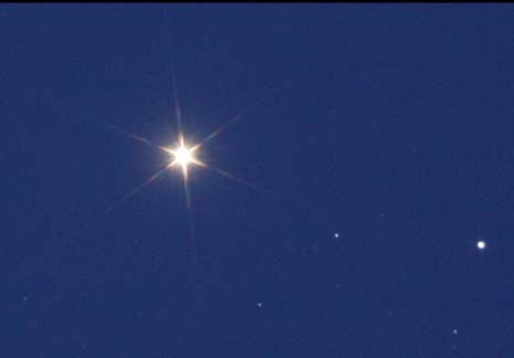
I finally managed to put the tracking circuitry in to proper action. I used EQAlign to verify my polar alignment and tracking speed. After a short (approx. 5min) testing of the tracking speed I was ready to take afew test photos. I installed the camera on the scope and linked it to the computer. LiveView on I used a bahtinov to get the focus correct. A few test shots of Arcturus .
Everything seemed OK. The wind and a full moon posed some minor problems, but nothing to dissuade me from the long awaited photo session. I originally planned on photographing the Pinwheel Galaxy (M101), but decided to go with a an easier target for the first try. So I went for the Hercules cluster (M13).
After getting the cluster in the finder cross hairs a few test shots again with various exposure lengths. I decided to go with 30s sub frames.

This was enough to see if the tracking was performing as it should. I ended up with 11 30s exposures like the one on the left. I also took 4 30s darkframes. After dragging everything inside some crunching with DSS (Deep Sky Stacker) to see if the images were really usable. I ended up using 6 of sub frames based on the score given by DSS to the individual sub frames. The final image with some minor image processing is shown below.I also manage to catch some unsuspecting visitor on one of the sub frames (a satellite most likely) and you can also see the galaxy designated NGC 6207 on the bottom left (which roughly towards the celestial north).

It seems that the new circuit is working well and is considerably steadier than the original. I still need to get the tracking speed set as precisely as possible. That means running the EQAlign for alonger period of time to see the drift.
Until next time.


0 comments:
Post a Comment